Creating a Screenspace Procedural Edge Flare Tool in Nuke

An edge flare is a sort of secondary lens flare that appears when a bright light source outside of the frame hits the lens. A lot of the time there might not be a flare at all when the light source is visible in frame, but as it exits and the light rays penetrate the glass from a glancing angle, a horizontal or vertical (depending on the edge of frame) flare will kick up, raising in value briefly until it hits an apex, then fading out again. At their subtlest, they might just be small glows, at the most extreme they can have complex caustic starburst effects, chroma split and entire frame contamination. When combined with a lens flare inside the frame, they can build up to be very complex optical phenomena.
Unlike a standard lens flare they can be slightly more complicated to reproduce synthetically, because you need to build in animation attributes such as the shape, brightness and complexity which all change based on the position in or outside of frame.


I wanted to document my experiments into creating a tool that will produce these flares, in a step-by-step process explaining the ideas behind the expressions and workflow.
You can download the current release of this tool on Nukepedia: http://www.nukepedia.com/toolsets/draw/ct_edgeflare
Proposed Edge Flare Tool
User input 2D position on-screen or an option to plug in a 3D axis and camera to reconcile a point
Lens distortion capabilities to take into account a UV map which will warp the 2D position
Controls to dictate the points in and out of frame that the flare will start to appear at and then fade out to
Brightness modulation using noise functions, taking the 2D position as an argument
Secondary flaring which kicks in as the main flare fades out
Flare shape created as procedurally and cheaply as possible
Edge-aware rotation so the flare always points in the correct direction (with options to define either top/bottom or left/right frame edges to flare from)
Part I: Creating the Flare Shape

Start by creating a reformat node — this will set the desired format for the flare. Connect an expression node after it, named Flare_Gen and create some user-defined variables:
flarePos, flareSize, flareSizeFalloff, flareSizeGain, penumbraFalloff, penumbraAngle, penumbraGain, aspect, rotate, inPoint, outPoint, easing, wavelength, offsetFlareX, offsetFlareY
We’ll need a few more later, but this should get us started.
To create the base shape of the flare, we’ll need to create a few separate shapes first which we’ll multiply together.
Radial
In the red channel, create a simple radial using the following. The pixel_aspect variable below (native to Nuke) calls the aspect ratio of the project format, which we’ll use to distort our radial to correctly display as a circle, even when being “un-squeezed” in an anamorphic project.
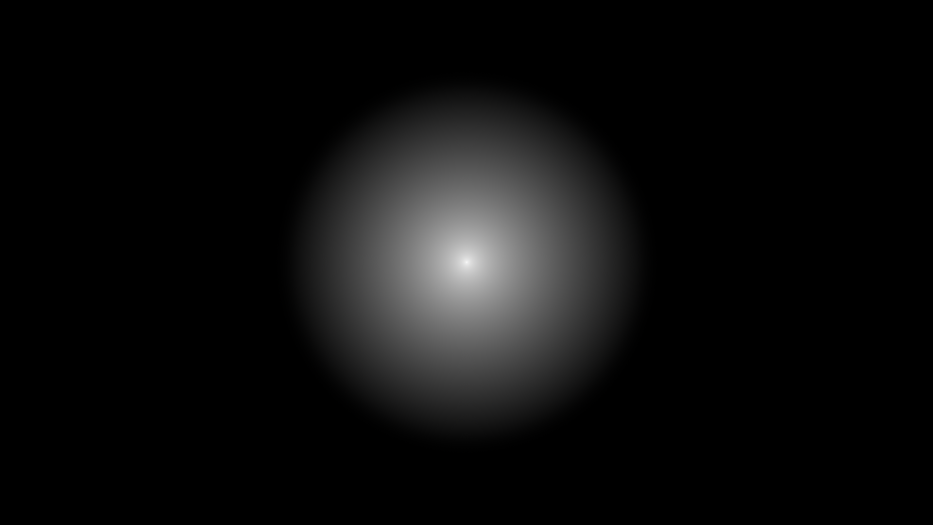
clamp((flareSize-(sqrt(hypot( ((x-flarePos.x)*pixel_aspect) , (y-flarePos.y) ))))/flareSize)
We now have a normalized radial that will define the size of the flare. To adjust the falloff of the shape, insert a gamma adjustment into the expression. Also multiply by the flareSizeGain to control the value. We’ll also add our offsetFlareX/Y into the expression:
(pow( (clamp((flareSize-(sqrt(hypot( (x-(flarePos.x+offsetFlareX)) , ((y-(flarePos.y+offsetFlareY))/pixel_aspect) ))))/flareSize)) , (1/flareSizeFalloff) )) * flareSizeGain
Set the flareSize to around 15, flareSizeFalloff to 0.5 and flareSizeGain to 1.
Radial Core
To create a slim, squashed version of this radial that will act as a hot core, enter the following into the green channel:

(clamp( (1/sqrt(hypot( ((x-(flarePos.x+offsetFlareX))*(pixel_aspect*aspect)) , ((y-(flarePos.y+offsetFlareY))/(pixel_aspect*aspect)) ))) , 0 , 2))
The only differences we’ve made from the original radial expression is to replace the flareSize with the value 1 which will give the radial exponential attenuation. We also will no longer divide by the flareSize as we don’t want to normalize it. We’ve fed the clamp function a 0 and a 2 which will limit the upper value (which is inf at the central pixel) to 2. The default clamp function when fed just an argument with no parameters will clamp from 0 to 1, so we feed it custom values.
Set the user aspect parameter to 3.
Penumbra Angle
The final shape we need is a radial gradient describing degrees around our flarePos. We’ll use this to define the penumbra angle of the edge flare.
Again, using similar parts of the above expressions we’ll create this in the blue channel:

(atan( ((x-(flarePos.x+offsetFlareX))*pixel_aspect) , (y-(flarePos.y+offsetFlareY)) ))
This will give us a radial gradient from 0–360. We then need to use the sine function to divide this into separate rays.
(sin( (atan( ((x-(flarePos.x+offsetFlareX))*pixel_aspect) , (y-(flarePos.y+offsetFlareY)) )) * wavelength + rotate))
Adjust your wavelength and rotate sliders to check this is working.
By setting our wavelength to 1, we’ll be left with a single positive ray covering 180 degrees. Setting rotate to -1.57 will flip our orientation to negative. We’ll use a blackpoint adjustment (subtract the penumbraAngle) to crunch the angle, clamp the result, gain up and implement a gamma adjustment (power function) for the falloff.
(pow( (clamp(((sin( (atan( ((x-(flarePos.x+offsetFlareX))*pixel_aspect) , (y-(flarePos.y+offsetFlareY)) )) * wavelength + rotate)) -penumbraAngle))*penumbraGain) , (1/penumbraFalloff) ))
Set the angle to around 0.7 and the falloff to around 0.5 and gain up by 3.
Assemble the Flare

We have all three component shapes — we can now multiply them all together. Shuffle out the red, green and blue channels respectively using three separate shuffle nodes and merge into one multiply node.
The last quick tweak we’ll make is to the rotation of the flare. Obviously if it moves from top to bottom of frame, it would need to flip at some point such that it orients correctly. Dive back into the expression node and create a pulldown choice slider called frameEdge, with “top/bottom” as the first list value and “left/right” as the second. Inside the expression for the radial gradient, replace the rotate variable with:
(frameEdge ? (flarePos.x > (width/2) ? (-3+rotate) : (0+rotate)) : (flarePos.y > (height/2) ? (-1.57+rotate) : -(-1.57+rotate) ))
The -3 and -1.57 values are only relevant if using the same wavelength value of 1 as I did above. Anything else and it’ll screw up. Alternatively just keep the rotate value as is, and manually rotate based on the position needed on screen.

Part 2: Edge Flare Animation
Arguably more important than the actual shape of the edge flare is the animation and behaviour of it, specifically ramping up the intensity as the user position nears the edge of screen, peaking at a point outside the frame then ramping down again. Once we’ve created this ramp we can use it to control other characteristics of the shape as well, such as the penumbra angle. We’ll even use some noise functions later to add variation to the brightness as the user position moves around the frame.
Intensity Ramp
Create the following user parameter floats, in addition to the existing ones in the expression node:
flareIntensity, linearRamp, rampBalance
Also create a 2d position parameter called cutPos.
We’ll use these to store variations of the flare position manipulated in different ways.
We’re going to want to be able to define the point on-screen at which the flare starts ramping up intensity and the point offscreen it dies. We’ll use the inPoint and outPoint parameters for this. We’ll also use the rampBalance as an exponent to offset the peak of the flare.
To start the curve for the X coordinates, set an animation on the flare position to make it travel from far left to far right off screen. Set a value of 50 for inPoint and -150 for outPoint. We’ll use an if-and statement to qualify the flarePos as either on or off. If it’s within the range of inPoint and outPoint then resolve the unchanged flarePos.x value, else resolve 0. Set this in the cutPos.x variable.
flarePos.x > (width-inPoint) && flarePos.x < (width-outPoint) ? flarePos.x : flarePos.x < inPoint && flarePos.x > outPoint ? flarePos.x : 0

The next step is normalizing the curve to between 0 and 1, for events on both the left side and right side of frame, as well as top and bottom. We’ll need different expressions for both.
By using an if-and statement, we’ve separated the expression into easy to manage sections. If we want to adjust the peaks describing a flare intersection on the right of frame, we can simply adjust our flarePos.x value within that part of the expression. The bold sections below are what we can change to normalize the curve for both left and right side intersections.
flarePos.x > (width-inPoint) && flarePos.x < (width-outPoint) ? flarePos.x : flarePos.x < inPoint && flarePos.x > outPoint ? flarePos.x : 0
Begin by subtracting (width-inPoint) from flarePos.x. This will set the base of the blip back to 0.

We can then divide by (inPoint-outPoint) to set the peak to 1.
The left side of frame is a little different as we’re dealing with both negative and positive X values (as the flare moves left offscreen into negative). We’ll flip the curve into the positive domain with flarePos.x*-1. We’ll then add our inPoint which will offset the curve vertically, shifting it out of the negative. As before, we can then divide by (inPoint-outPoint) which will set the peak to 1.

We’ll be left with the following linear ramps.

The left spike describes the flare moving from the far left into frame, and the right shows the flare moving out of the right side of frame until it passes the out point and becomes 0.
This is the final expression needed:
flarePos.x > (width-inPoint) && flarePos.x < (width-outPoint) ? (flarePos.x-(width-inPoint)) / (inPoint-outPoint) : flarePos.x < inPoint && flarePos.x > -outPoint ? ((flarePos.x*-1) + inPoint) / (inPoint-outPoint) : 0
Now duplicate this expression for the cutPos.y parameter too, replacing x with y and width with height.
Next we need to combine the two floats cutPos.x and cutPos.y into one float. We’ll do this by using a max function to take the maximum value of either float. Put the following into the linearRamp parameter:
max(cutPos.x , cutPos.y)
We can use this value for adjusting the penumbra angle and noise expression later on.
As mentioned before, we need to transform these curves into something smoother, modifying the curves to look more like arches than spikes, with values ranging from 0 to 1 to 0.
Moving on to the main parameter, flareIntensity, we’ll pipe in the linearRamp and do the following inversion trick:
(linearRamp * (1-linearRamp) ) * 4

We’ve now got a smooth ramp that starts at 0, peaks at 1 and then rests at 0 again.
We’ll now modify our linearRamp expression to offset the center of the peak of the arc, using the rampBalance exponent — right now the peak is perfectly in the middle of the ramp. We might want to make it less “perfect”. Do the following in the linearRamp parameter:
pow( (max( cutPos.x , cutPos.y )) , (1/rampBalance) )
Now we can lean the peak of the curves to the left or right slightly. As a side note, the nature of the exponent adjustment means that using rampBalance values less than 1 will give different results to using values above 1. The following expression mitigates this slightly, though it’s a bit of a hack (I’m using a reversed rampBalance value for when a value of less than 1 is entered, then applying that to an inverted curve, then inverting the whole thing back at the end). Use the following fix if you want to.
rampBalance < 1 ? (1-(pow( (1-(max( cutPos.x , cutPos.y ))) , (rampBalance) ))) : (pow( (max( cutPos.x , cutPos.y )) , (1/rampBalance) ))
The final tweak to make to the flareIntensity value is to smooth out and taper the response — easing in and out. A quick way to do this is to use another exponent adjustment, essentially gamma down our curve. We’ll use the easing (set to about 0.1) parameter as our exponent.
pow( ((linearRamp * (1-linearRamp) ) * 4) , (1/easing) )

We’ve now got a couple of values to drive the flare behaviour with — the obvious and most important would be to connect a Multiply node to the Flare_Gen node and use the flareIntensity ramp as the value. Now whenever the flare moves offscreen, the brightness will peak then dissipate.
Part 3: Building the Tool
Visualization
The first thing we’ll do is set up a visual aid in the tool so we can visualize where the flare begins and ends. Luckily as we’ve used real position values to create the linearRamp we can use some bounding boxes to mark the entry/exit. Create two Bounding Box Knobs on the expression node called flareVisualizeIn and flareVisualizeOut.
flareVisualizeIn:
x: inPoint y: height-inPoint r: width-inPoint t: inPoint
flareVisualizeOut:
x: width-outPoint y: height-outPoint r: outPount t: outPoint
The UI should look like the following:

Noise Modulation
To modulate the intensity, creating a flicker based on the position of the flare, we’ll need to use a noise function. Create 3 new variables in the Flare_Gen node called flareModulation, modulationAmp (set to about 0.2) and modulationWavelength (set to about 20). Type the following into flareModulation:
(noise(linearRamp*modulationWavelength))*modulationAmp
We’ll multiply our flareIntensity float with this flareModulation value (adding 1 first so as to modulate only from a base of 1). The flareIntensity expression will now look like:
(pow( ((linearRamp * (1-linearRamp) ) * 4) , (1/easing) ) ) * (1 + flareModulation)
The flare will now flicker subtly as the flarePos moves across frame.
Penumbra Angle
Next we’ll adjust the penumbraAngle (cone effect) of the flare using the linearRamp value. We want the flare to close into a smaller cone angle the further out the flarePos gets, and open wider when it’s coming into frame.
Set the penumbraAngle to:
linearRamp*2
You can ramp up the value “2” if you want a faster cone closure effect.
Flare Aspect
We’ll increase the aspect value as well as the flare edges out of frame, so as to make the flare sharper. The following will multiply the linearRamp above one, then gamma down to add contrast to the animation, finally adding a residual value so the bottom isn’t 0.
(pow((linearRamp*3),(1/0.5)))+2
Result

We’ve now created the base flare to which we can now add any number of additional optical elements to, making use of the linearRamp and flareIntensity values for animation purposes.
After packaging everything up into a group, exposing certain important sliders and dressing in more detail such as chroma caustics, I achieved the following:

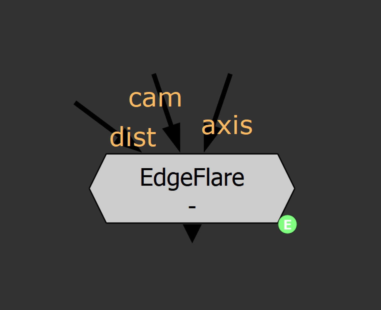

The completed tool takes optional axis/cam inputs for defining the point on-screen automatically. The dist tab imports a lens distortion stmap to influence the point position. Buttons analyze and clear keys for each frame.
You can toggle on/off the edge border visualizers to eyeball where the flare should begin and end. The other toggle reveals the normalized flare intensity float in case it’s needed for any extra animations.
I added various other animations and chroma effects to finesse the flare.